
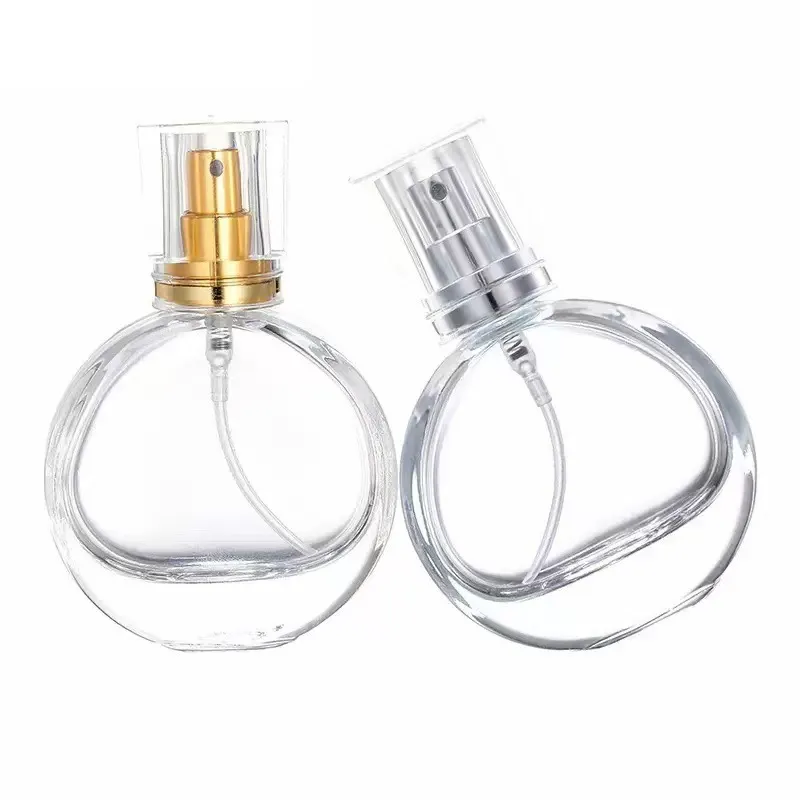
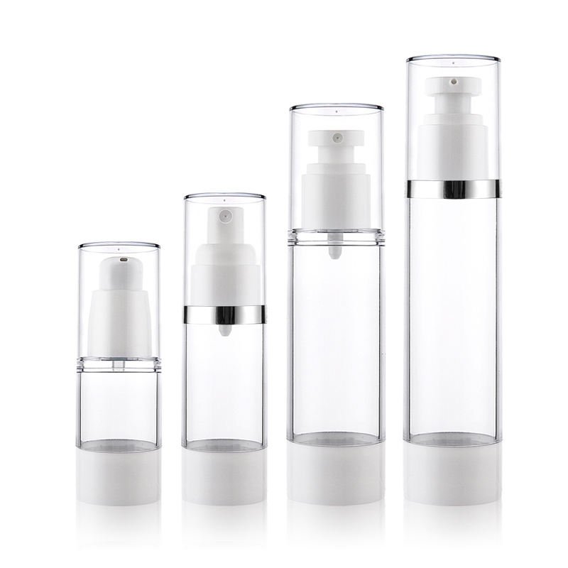
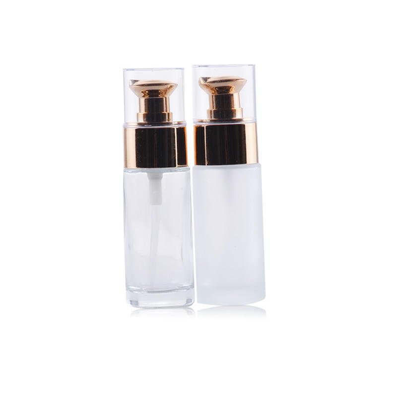
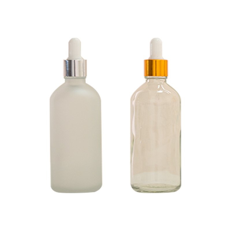


핵심 답변: a cap can feel tight and still leak because torque measures turning resistance—not seal integrity or gasket compression directly. The leak may come from cross-threading, a damaged sealing land, a folded or chemically incompatible liner, product on the seal, a mismatched neck finish, plastic relaxation, thermal pressure or another leak path such as a pump vent. Do not keep increasing torque. Establish a package-specific operating window: the minimum must pass filled-product leak and distribution tests after conditioning, while the maximum must remain below thread damage, seal distortion and unacceptable opening force. A cap-diameter chart is only a trial starting point.

Why can a tightly screwed cap still leak?
Threads convert rotational input into downward movement and seal loading, but the conversion depends on thread geometry, friction, cap stiffness, bottle finish, liner or molded seal, contamination and how far the closure actually travels. A high torque reading can therefore come from thread drag or cross-threading before the sealing element makes uniform contact. Conversely, a lower measured opening torque does not prove leakage if the intended seal remains compressed and stable.
The correct question is not “How hard was the cap tightened?” but “At what validated application range does this exact filled package remain sealed, undamaged and openable after time and distribution?” ASTM D2063/D2063M-24 measures removal torque of matching continuous-thread systems under predetermined environmental conditions over time. It is a torque-retention method; passing a torque limit is not itself a leak test.
| Leak mechanism | Why the cap may still feel tight | 확보할 증빙 | 시정 방향 |
|---|---|---|---|
| Cross-thread or early skirt bottoming | Thread interference or skirt contact creates resistance before adequate seal load develops. | Cap height, pull-up/index marks, thread witness, torque-versus-angle trace and matched drawings. | Correct finish match, alignment, capper chuck/top load or component dimensions; do not add torque. |
| Uneven or damaged sealing land | The closure seats, but a chip, seam, flash, ovality or nick leaves a local flow path. | Magnified land inspection, dimensional mapping by mold cavity and seal-contact witness. | Correct the bottle finish or reject affected cavities/lots; torque cannot repair a defective land. |
| Liner, gasket or plug-seal failure | A missing, folded, cut, swollen, compressed or dimensionally wrong seal can coexist with normal thread resistance. | Seal presence/orientation, compression witness, thickness, hardness, lot identity and aged compatibility. | Restore the specified seal, material and geometry; validate contact at low and high torque limits. |
| Product on the land or threads | Wet formula may lubricate application; dried product may later increase opening drag while preventing clean seal contact. | Nozzle cut-off, fill height, capper timing, clean-versus-contaminated controls and leak location. | Control splash/stringing and clean the interface; do not define the range using deliberately contaminated samples unless that state represents foreseeable production. |
| Relaxation or cap back-off | The cap was tight at application, but polymer or liner stress relaxes and vibration/thermal cycles reduce retained seal load. | Immediate and delayed T1, cap/bottle position marks, conditioned samples and head-by-head line data. | Optimize material/seal design and application window; validate after ageing and distribution. |
| Leak path outside the threaded seal | A pump vent, actuator, hinge, weld, pinhole, bottle seam or induction-seal defect is unaffected by more collar torque. | Dye or bubble location where appropriate, component isolation, known-good substitutions and mass-loss trend. | Repair the actual component or process; use torque only where it controls that interface. |
A practical eight-step diagnosis before changing torque
- Quarantine and preserve evidence. Record the line, time, capper head, bottle cavity, component lots, fill batch, fill temperature, pack orientation and distribution history. Do not retighten failed units before inspection.
- Locate the leak path. Separate neck/land leakage from product emerging through a pump vent, nozzle, hinge, bottle seam or decoration defect. Photograph wetting and mark cap-to-bottle position.
- Confirm what “tight” means. Identify whether the value is capper setting, controlled application torque, immediate T1 or delayed T1. Repeat with a calibrated, correctly ranged tester and a fixed interval.
- Check seating before numbers. Inspect tilt, cap height, pull-up, cross-threading, skirt interference, tamper-band engagement and whether the pump collar—not the actuator—was gripped.
- Inspect the sealing interface. Look for missing/folded liners, cut gaskets, poor compression witness, land flash, chips, ovality and formula residue.
- Run a crossover matrix. Assemble suspect bottles with known-good closures and suspect closures with known-good bottles. This does not prove root cause by itself, but it efficiently separates component-side patterns.
- Compare dry and filled controls. Use the actual formula and production fill condition to reveal lubrication, chemical interaction, foam, thermal effects and headspace pressure that empty-pack testing misses.
- Challenge the proposed correction. Test low, target and high application levels after the defined dwell, orientation, temperature cycle, vibration/drop or reduced-pressure exposure. Confirm leakage, openability, dispensing and physical damage together.
What does bottle cap torque mean?
Torque is a turning moment: force acting at a distance from an axis. In packaging, it describes either the rotational input used to seat a threaded closure or the resistance measured while opening it. Torque is not the same as vertical top load, liner compression, seal pressure or the force needed to pull off a snap cap, although these variables may interact.
Common packaging units are lbf·in, N·cm 및 N·m. The multiplication dot matters: “in-lb” or “inch-pound” is torque, not pounds per inch. Useful conversions are:
1 lbf·in = 11.30 N·cm = 0.1130 N·m
1 N·m = 8.851 lbf·in
Example: 14 lbf·in × 0.1130 = approximately 1.58 N·m.
A torque number without context is incomplete. “12 lbf·in” could mean torque applied by a laboratory operator, immediate breakaway torque, the torque after 24 hours, or thread-strip torque. Those results answer different questions. The component codes and test conditions must accompany the value.
The main bottle cap torque measurements
| 측정 | 측정 대상 | 중요한 이유 | 흔한 실수 |
|---|---|---|---|
| Application torque | Rotational input while tightening the cap. | Creates thread engagement and seal compression. | Treating the capper clutch setting as the torque actually delivered to every pack. |
| Breakaway / removal torque (T1) | Peak required to initiate cap rotation after a defined dwell. | Relates to opening experience and retained tightness. | Comparing immediate results with 24-hour results as if they were equivalent. |
| Running torque | Resistance after first movement while the cap continues to turn. | Reveals thread drag, ovality, deformation or contamination. | Reporting it as breakaway torque. |
| Bridge-break torque (T2) | Peak associated with breaking tamper-evident bridges or releasing the band. | Confirms opening sequence and tamper-band behaviour. | Letting a manual peak display capture T2 when the specification calls for T1. |
| Strip / override torque | Torque at which the thread jumps, spins or suffers damage. | Defines an upper mechanical limit and design margin. | Using saleable components without a destructive-test plan. |
| Torque retention | How opening torque changes after a stated time and environment. | Detects relaxation, liner change, temperature effects and product interaction. | Calling one reading a “retention” result without baseline and interval. |
What is the recommended torque for caps?
The defensible answer is a validated range, not one universal number. For ordinary continuous-thread closures, industry guides commonly use an initial application-torque rule of roughly one-half the closure diameter in millimetres, expressed in lbf·in. A 28 mm cap would therefore begin near 14 lbf·in (about 1.58 N·m). This is a screening estimate—not an ASTM requirement, a consumer-opening limit or a release specification.
The following broad values are useful for planning early trials. They combine commonly published glass/plastic closure guidance and intentionally remain wide. The closure supplier’s current technical data sheet and testing on the exact pack control the final decision.
| Nominal cap diameter | Broad application-torque screen for plastic containers | Approx. SI range |
|---|---|---|
| 15 mm | 7–9 lbf·in | 0.79–1.02 N·m |
| 20 mm | 10–12 lbf·in | 1.13–1.36 N·m |
| 24 mm | 12–15 lbf·in | 1.36–1.69 N·m |
| 28 mm | 13–17 lbf·in | 1.47–1.92 N·m |
| 33 mm | 16–20 lbf·in | 1.81–2.26 N·m |
| 38 mm | 19–23 lbf·in | 2.15–2.60 N·m |
| 43 mm | 21–26 lbf·in | 2.37–2.94 N·m |
Use limitation: preliminary continuous-thread guidance only. Finish series, cap design, resin, liner, seal geometry and product can justify values outside these ranges. Do not use this table for crimped perfume pumps, snap caps, ROPP forming settings, press-on/twist-off caps, child-resistant certification or dangerous-goods closure approval.
How to establish the real torque window
- Start with matched drawings and supplier data. Confirm the full neck finish, not only diameter. A 24/410 cap is not proven on a 24/400 bottle. Boyu’s 플라스틱 병 넥 규격 가이드 explains the critical dimensions.
- Define failure at both ends. The lower boundary must resist leakage, back-off and loss of seal. The upper boundary must avoid thread damage, package distortion and unacceptable opening effort.
- Run a designed trial. Apply several controlled torque levels to production-intent components, using relevant lots and cavities. Include the actual liner, gasket, induction seal or plug seal.
- Condition and challenge the packs. Measure immediate and specified-dwell removal torque; then evaluate leakage, compatibility, temperature cycling and distribution as appropriate.
- Set operating and alert limits. Choose a target with margin from both failure boundaries. Correlate the capper’s settings and heads with package readings; document the method, timing, sample plan and response rules.
Do not set the minimum from leakage alone or the maximum from stripping alone. Consumer openability may become limiting before the thread strips, and a cap can be tight yet leak because the liner, land or finish is defective.
How do you measure bottle cap torque?
ASTM D2063/D2063M covers torque retention for matching continuous-thread container/closure systems using manual equipment. ASTM D7860 covers automated, transducer-based measurement under defined rotation. ASTM D3474 addresses calibration and use of packaging torque meters. Older specifications often cite ASTM D3198 for application and removal torque; ASTM lists that method as withdrawn in 2016, so contracts should state the required edition or replace it with an agreed current procedure.

A repeatable removal-torque procedure
- Write the sample identity. Record bottle, cap and liner part numbers; materials; finish; mold or cavity where available; component lots; fill; capper head; and whether an induction seal or tamper band is present.
- Define the sample state. State whether packages are dry or filled, upright or stored on the side, and whether product is present on the land or threads. Record filling and capping time.
- Fix the test interval and environment. Immediate, 30-minute, 24-hour and aged readings are not interchangeable. Record conditioning time, temperature and any environmental exposure.
- Verify the instrument. Use an in-range calibrated tester, correct units, zero check and an appropriate fixture. A reading near the bottom or top of the instrument range may be less useful than one taken on a correctly sized sensor.
- Center and restrain the bottle. Clamp the body firmly enough to prevent movement but not so hard that a thin-wall bottle deforms and changes the neck geometry.
- Grip the closure squarely. Avoid a slipping hand, off-axis pull or fixture contact with the tamper band unless the method requires it.
- Open in a smooth, defined motion. For manual testing, control operator technique and direction. For motorized testing, specify rotational speed and any top load. Record the intended event—usually first movement for T1—not simply the largest peak on the display.
- Inspect after testing. Note cap slip, bottle movement, cross-threading, damaged bridges, liner adhesion, wet threads or abnormal drag. Invalidate and repeat any test compromised by fixture or technique.
For application-torque studies, use a controlled applicator or torque head to apply known inputs, then measure opening torque at the agreed intervals. A production capper may control clutch current, chuck pressure, belt speed, head load or servo profile rather than directly reporting the torque delivered to the pack. The production correlation must be demonstrated, not assumed.
What data should be reported?
A decision-grade report includes the method and revision; tester identity, range and calibration status; units; fixture; speed or manual technique; top load if used; sample count; bottle and closure IDs/lots; formula; application method and target; elapsed time; conditioning; individual results; mean, range and standard deviation; abnormal observations; acceptance criteria; failures; and authorisation. For tamper-evident closures, retain the torque-versus-angle trace when it is needed to distinguish T1 from T2.
Manual, motorized and inline torque testing
| 방법 | 장점 | 제약 사항 | 적합한 구매자·프로젝트 |
|---|---|---|---|
| Manual digital or dial tester | Low cost, fast, reflects hand opening, easy at line-side QC. | Operator speed, grip and peak selection add variability. | Routine checks after operator qualification and gauge R&R. |
| Motorized tester | Controls speed, captures torque-angle data and separates events more consistently. | Higher cost; fixture and programmed method still require validation. | Development, investigations, TE/CRC event analysis and high-precision QC. |
| Automated / inline system | High sample frequency, reduced handling, head or lane trend data. | Capital, integration and method-correlation requirements; destructive opening may remove product. | High-speed lines and processes needing rapid SPC feedback. |
Manual and automated values may differ because speed, gripping and event detection differ. Silgan advises a gauge repeatability and reproducibility study when an automated opening device replaces hand removal for a published manual range. Treat the change as a measurement-system change and correlate both methods before changing acceptance limits.
How bottle, cap and liner materials affect torque
Material affects friction, stiffness, dimensional stability, creep, seal recovery and sensitivity to temperature. However, “PET needs X” or “glass needs Y” is too simple. The closure resin and sealing design often affect torque retention as much as the bottle resin.
| 소재 / 시스템 | Torque-relevant behaviour | Practical control |
|---|---|---|
| 유리병 | Rigid and dimensionally stable, but finish variation, seams, chips and surface treatment can affect engagement and friction. Excessive force can damage a defective or unsuitable finish. | Inspect sealing land and finish; use the closure maker’s glass recommendation; never compensate for chipped glass with more torque. |
| PET 용기 | Relatively stiff neck, but heat, top load, lightweighting and stress can change geometry. Plastic still relaxes over time. | Test after filling, cooling and temperature conditioning; monitor finish dimensions and top-load deformation. |
| HDPE / LDPE bottle | More compliant; body clamping, finish ovality, molding shrinkage and creep may affect readings and seal load. | Use non-distorting fixtures, cavity sampling and ageing checks; do not transfer a PET window unchanged. |
| PP or PE closure | Resin stiffness, coefficient of friction, wall design, pigments and processing influence thread response and relaxation. | Approve the exact closure resin and supplier; requalify material, colorant, tooling or lightweighting changes. |
| Lined closure | The liner compresses and conforms; compression set, recovery, adhesion and chemical swelling can change removal torque. | Specify liner compound and thickness; test after dwell, heat and formula contact. |
| Linerless plug, bore or crab-claw seal | Seal depends directly on molded geometry, interference and material recovery rather than a separate liner. | Control bore/land dimensions and seal feature; validate leakage over temperature and ageing. |
| Metal closure | Lug, twist-off and roll-on formats combine metal deformation, gasket/compound, vacuum and glass finish effects; a simple plastic screw-cap chart does not apply. | Use closure-specific pull-up/security, roller or sealing-shoe settings and vacuum checks where applicable. |
The filled product also changes the interface. Surfactants, oils or silicones on the threads can lubricate and lower application friction; dried formula can add drag; solvents can swell a gasket or attack a coating; elevated temperature can accelerate relaxation. Include torque checks within 제형·패키지 적합성 시험, not only on clean empty components.
Bottle cap torque by closure type

| 마개 | 장점 | Torque risks | Typical products |
|---|---|---|---|
| Lined continuous-thread cap | Adaptable seal and broad chemical options. | Liner compression/relaxation, adhesion, contamination. | Lotions, shampoos, oils, powders and treatment products. |
| Linerless plug or bore-seal cap | Fewer components and potential mono-material design. | Dimensional interference, stress relaxation, finish damage. | Shampoo, toner and compatible aqueous personal care. |
| Flip-top / disc-top | Convenient controlled dispensing. | Threaded base can be under- or over-applied; hinge/lid function is a separate test. | Shampoo, conditioner, body wash and lotion. |
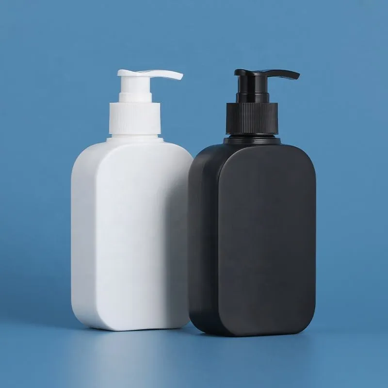
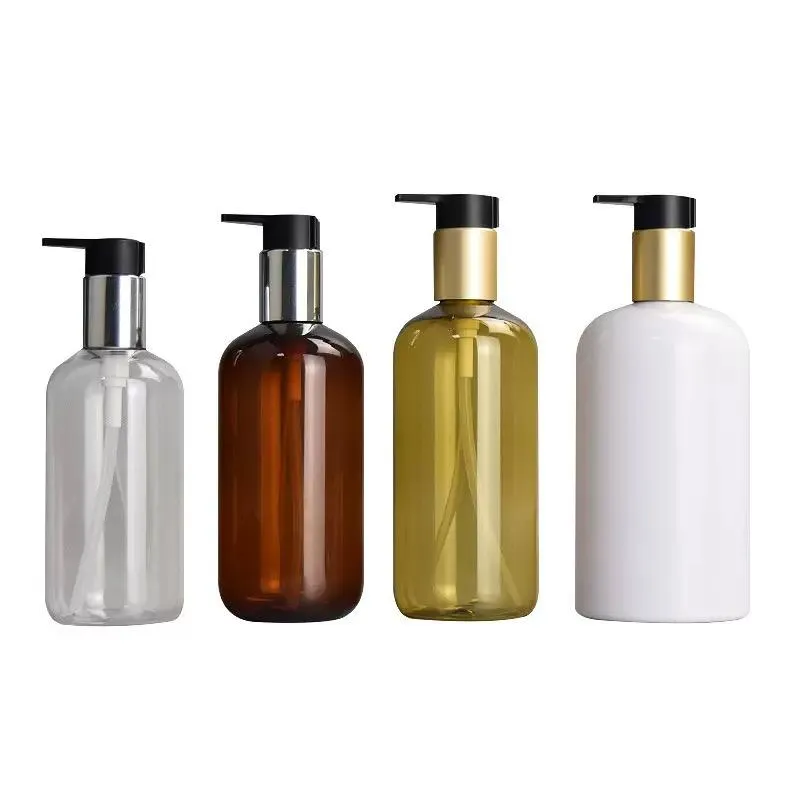
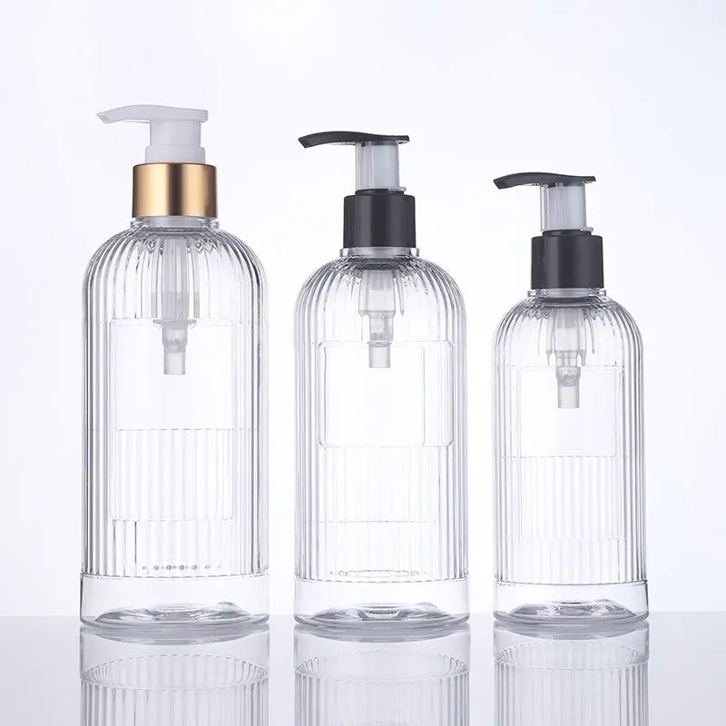
| Pump or sprayer collar | Dispensing plus reclosable threaded assembly. | Collar can rotate while actuator is locked; gasket, vent and engine may be damaged by excess assembly force. | Lotion-bottle packaging, hand soap, serum and fine mist. |
| 어린이 안전 잠금 장치 | Access-control mechanism for applicable hazardous products. | Requires defined top load and opening sequence; torque alone cannot prove child resistance or adult usability. | Regulated or risk-assessed household, pharmaceutical and certain chemical products. |
| Metal lug / twist-off | Fast partial-turn closure with compound seal. | Vacuum, glass treatment, lug security and compound affect opening; rotation alone is not the whole control plan. | Food, beverage and specialty jars. |
| Snap-on or crimped closure | Fast assembly or premium low-profile finish. | Ordinary screw-cap application torque does not apply; use pull-off, snap force, crimp diameter/height or format-specific opening tests. | Overcaps, some cosmetics and crimped perfume pumps. |
How product and use scenario change the specification
- Shampoo, body wash and surfactant products: product on the finish can reduce friction during capping and later dry into added drag. Include wet-thread and filled-pack challenges where foreseeable.
- Lotions and creams: pumps and disc-tops need both collar-torque and dispensing tests. High viscosity does not justify more collar torque; gasket contact and pump venting must be correct.
- Oils, essential oils and solvent-rich formulas: evaluate liner/elastomer compatibility, swelling, stress cracking and lubrication. A dry-water test cannot approve the final pack.
- Alcohol-based sprays: test evaporation loss, gasket and actuator compatibility, closure back-off and decoration resistance after formula contact.
- Hot-filled or warm-filled products: measure after the complete fill, cap and cooling process. Thermal expansion, bottle softening and liner behavior can make room-temperature empty-pack data misleading.
- E-commerce and export distribution: combine retained torque with vibration, drop, altitude/reduced-pressure and temperature-route tests as justified. The final shipper and pack orientation matter.
Torque is one line in a broader qualification matrix. Use a complete cosmetic bottle test plan to connect fit, torque, leakage, dispensing, compatibility and distribution performance.
How temperature, pressure, time and transport change the seal
A torque range approved immediately on a room-temperature bench may fail after filling or shipping. Environmental conditions change the package in several ways at once, so retain control samples and compare torque, leak location, mass change and component condition—not torque alone.
- Heat: plastic closures, liners and compliant bottle finishes can relax or deform; formula and trapped headspace expand; hot or warm product may reduce bottle stiffness during capping. Apply and measure at defined process points, then retest after cooling and heat conditioning.
- Cold: materials and elastomeric seals may become stiffer while formula viscosity increases. This can alter measured opening torque and may expose brittle damage or poor conformity. Compare at a defined recovery condition as well as at the intended cold-use condition when relevant.
- Reduced external pressure or altitude: the pressure difference across the closed package can drive liquid or vapor through a marginal seal. Headspace, fill temperature, formula volatility and package flexibility all matter; a torque result cannot predict the pressure differential by itself.
- Vibration and impact: repeated motion can promote cap back-off, pump unlocking, thread movement or splash onto the sealing interface. Mark cap position and measure retained torque before and after a distribution sequence using the final carton and orientation.
- Time: polymer stress relaxation, liner compression set, formula absorption and evaporation can change both retained torque and seal performance. Define immediate, delayed and aged checkpoints instead of comparing samples with unknown dwell.
- Humidity: its importance depends on the liner, paper-backed materials, carton and product. Do not assume it changes every plastic cap; include it when the material system or distribution route gives a credible moisture-related risk.
Protect the finished pack by controlling sealing-surface cleanliness, fill/headspace, capper alignment, application limits and component traceability. A liner, induction seal, plug seal, tamper feature, overcap, locking clip or carton restraint may add useful protection when appropriate, but each has its own process controls. Secondary packaging should not be used to excuse a primary package that leaks under its approved conditions.
How to determine the minimum, target and maximum torque
- Define the system. Freeze bottle, closure, finish, liner/gasket, component materials, formula, fill, capper, distribution route and consumer-opening requirement.
- Select trial levels. Use the closure supplier’s current technical recommendation and any diameter-based rule only to bracket several controlled application settings. Include relevant molding cavities and material lots.
- Establish the lower boundary. Identify the lowest input that produces correct seating and passes filled leakage, formula compatibility and distribution challenges after the defined conditioning period. Add justified process margin rather than declaring the first passing sample the minimum.
- Establish the upper boundary. Identify the onset of thread override, finish deformation, liner damage, pump impairment or unacceptable consumer opening. Destructive strip testing belongs in development, not routine testing on saleable units.
- Choose a centered operating target. The production range must fit between the validated boundaries with allowance for capper-head, component and measurement variation. If no practical window remains, redesign the bottle–closure–seal system.
- Correlate and monitor. Relate capper settings to immediate and delayed package measurements, then trend results by head, cavity, lot and time. Revalidate after any controlled change that can alter friction, dimensions or seal behavior.
Bottle cap torque problems: causes and corrective actions
| 증상 | 가능한 원인 | Best next checks | Do not |
|---|---|---|---|
| Leak despite “correct” torque | Damaged land, wrong finish, cross-thread, folded/missing liner, gasket or bore-seal mismatch, bottle seam, formula attack. | Inspect seal witness and finish; cross-over suspect and known-good components; run appropriate 화장품 용기 누설 시험 방법. | Increase torque until the symptom disappears. |
| Low removal torque | Underapplication, bottle spinning, worn head/chuck, relaxation, hot pack, lubricant or product on threads, wrong liner. | Compare immediate and dwell results; segregate by capper head and component lot; check cap height/pull-up and finish cleanliness. | Assume every low value will leak. |
| High removal torque | Overapplication, excessive capper load, cross-threading, liner adhesion, dried product, distorted finish or low-temperature test. | Inspect threads and liner; review torque-angle curve; compare dry/filled controls and defined temperature. | Reduce torque before confirming seal integrity at the lower setting. |
| Large result variation | Mixed dwell times, operator motion, slipping fixture, bottle ovality, cavity differences, head wear, cap/liner variation. | Gauge R&R; standardize timing; plot by operator, cavity and capper head; verify tester range and calibration. | Average away identifiable special causes. |
| Cap backs off in shipment | Low retained torque, vibration, poor thread match, insufficient seal friction, compression/rebound or thermal cycling. | Mark cap/bottle position; measure before and after distribution; verify finish and liner; assess secondary retention features. | Rely on one upright static leak test. |
| Threads strip or cap spins | Overtorque, finish mismatch, shallow engagement, thin/deformed threads, overheated component. | Confirm drawings and engagement; measure destructive strip torque on controlled samples; calculate design margin. | Release stripped or partially jumped threads because the cap looks seated. |
| Pump collar rotates or leaks | Inadequate collar torque, gasket/land mismatch, wrong neck height, product lubrication, actuator used as tightening grip. | Grip the collar correctly; inspect gasket compression and vent; test locked/unlocked handling and distribution. | Judge the assembly only by pump output. |
A practical cap-torque quality-control plan

- At line setup: verify component codes, finish match, capper tooling, sensor/tester status, target and head-by-head output. Check seating, cap height or pull-up where relevant.
- At start-up and after downtime/changeover: take samples from every head or lane where traceable. Test at the defined immediate interval and retain a second set for the specified dwell reading.
- During production: sample at a risk-based frequency and after jams, adjustments, component-lot changes or abnormal trends. Plot results rather than recording only pass/fail.
- At release: combine torque with visual, cap-height/pull-up, leakage and function checks. Torque within limits cannot override a critical seal defect.
- During validation and change control: repeat filled-pack ageing, compatibility and distribution checks after changes to the bottle, cap, liner, resin, colorant, tooling, capper, fill temperature, formula or pack-out.
Define a reaction plan before the line runs: hold the affected interval, identify the last known good check, segregate by head or lot, correct the special cause, recheck and document disposition. Avoid repeatedly moving the capper setting in response to individual noisy readings; first confirm the measurement system and trend.
What buyers should put in a bottle-and-cap specification
Ask for evidence that identifies the whole system, not a generic cap chart. A useful purchase or qualification specification contains:
- bottle and closure drawings, revision levels and complete neck-finish designation;
- bottle, cap, liner/gasket and seal materials, including approved resin/colorant grades;
- supplier-recommended application range and the package-specific basis for it;
- defined opening-torque event, units, tester/method, interval, conditioning and acceptance range;
- destructive strip/override evidence or other upper-limit rationale during development;
- filled-product compatibility, leakage, dispensing and distribution acceptance criteria;
- sampling by relevant mold cavity, component lot and capper head;
- calibration, raw-data, traceability, retained-sample and change-notification requirements;
- market-specific CRC, tamper-evident, transport or dangerous-goods evidence where applicable.
When requesting a quote, provide the formula family, viscosity, solvent/oil/alcohol content, fill temperature, neck finish, closure type, induction seal or liner, market, distribution route and expected line speed. If you are developing a cosmetic bottle and closure together, send Boyu the bottle, closure and formula brief so the sample and test plan can be matched to the real application.
자주 묻는 질문
Is application torque the same as removal torque?
No. Application torque is the input used to tighten a closure. Removal torque is the opening resistance measured later. Material relaxation, liner compression, friction, temperature, product contact and elapsed time mean they are correlated only through a package-specific study.
What is the formula for recommended bottle cap torque?
A common screening rule is application torque in lbf·in ≈ closure diameter in mm ÷ 2. It is not a universal formula or acceptance standard. Use it to choose initial trial levels, then validate a minimum/target/maximum for the exact package.
How long should I wait before measuring removal torque?
Use the interval stated in the approved specification. Immediate readings help control capping; a defined later reading—often after a dwell such as several hours or 24 hours in company protocols—shows retained opening torque. The exact interval must be validated and reported; results from different intervals should not be pooled.
Does higher torque always prevent leakage?
No. Excess torque can strip threads, distort a plastic finish, damage a seal or make the package hard to open. Leakage may come from the wrong finish, damaged land, missing/folded liner, gasket incompatibility, a bottle defect or formula attack. Diagnose the interface rather than tightening blindly.
Can the same torque be used for glass and plastic bottles?
Not automatically. Glass and plastics differ in stiffness, dimensional variation, surface treatment, creep and damage modes. Published tables often give different starting ranges, and the closure/liner design may dominate. Approve each bottle–closure combination separately.
Can a handheld torque wrench replace a cap torque tester?
A suitable calibrated wrench can support controlled application or some manual methods, but a bottle fixture and appropriate cap adapter are needed for repeatability. A bench tester is normally better for opening QC because it restrains the bottle and captures peak events. Whatever equipment is used must be within range and included in the approved method.
Does a child-resistant cap pass if its torque is within range?
No. Torque and top load are relevant engineering parameters, but child resistance and adult accessibility require the applicable package design and test protocol. Do not infer a legal or performance claim from an ordinary torque check.
Need a torque-ready cosmetic bottle and closure?
Boyu Packaging can coordinate the bottle finish, cap or pump, gasket/liner, decoration, samples and production inspection as one packaging system. Share your formula profile, fill process, closure concept, target market and quantity for a project-specific recommendation.
출처
- ASTM International — D2063/D2063M-24, torque retention for continuous-thread closures using manual equipment
- ASTM International — D7860-14(2022), automated torque-retention testing
- ASTM International — D3474-23, calibration and use of torque meters in packaging
- ASTM International — D3198 historical record (withdrawn 2016)
- Silgan Closures — Plastic Closure Quality Checks, Technical Assistance Bulletin 014
- Silgan Closures — Glossary of Common Terms for plastic, steel and aluminium closures
- Industrial Physics — Torque Testing Guide
- Mecmesin — motorized closure torque testing and operator-variability considerations
- O.Berk — Bottles and Closures Application Torque
- International Labmate — Torque Tables for Screw Caps


 English
  Español de Argentina
  Русский
  Italiano
  日本語
日本語  한국어
한국어  العربية
  Français
  Deutsch