


Short answer: industrial glass is made by accurately weighing silica sand, soda ash, limestone or dolomite, alumina-bearing materials and clean recycled glass; melting and refining the batch in a continuous furnace; cooling it to a controlled forming viscosity; shaping it; and annealing it through a controlled cooling curve. In a bottle plant, the conditioned glass is cut into measured gobs, formed into a parison, blown into the final mould, annealed, inspected and packed. The process is controlled by viscosity and heat history—not by one universal temperature.
The temperature distinction that prevents expensive mistakes: a container furnace may operate around 1,550–1,600°C; a conditioned glass gob may be around 1,100–1,200°C; and a container annealing lehr may reheat ware to around 580°C. These are different stages and published industrial examples, not a recipe. Actual setpoints depend on composition, viscosity curve, bottle mass and geometry, furnace design, line speed, mould cooling and the validated annealing schedule.
Safety: this article describes an industrial process. Molten glass, combustion systems, refractory dust, moving IS machinery and compressed air require engineered controls and trained operators; this is not a home glassmaking procedure.
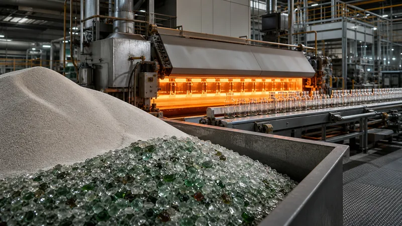 Container glass production is a continuous flow: controlled batch in, homogeneous conditioned glass through forming, then annealed and inspected bottles out.
Contents
What Is Glass, Technically?
Glass is an amorphous solid: its atoms lack the long-range repeating crystal structure found in a crystalline mineral. The raw materials react and dissolve into a homogeneous melt; controlled cooling then lets the material become rigid without crystallising. Contrary to a persistent myth, an ordinary room-temperature bottle is not a liquid slowly flowing under gravity.
“Glass” is a family, not one composition. Window glass, borosilicate laboratory glass, aluminosilicate cover glass and fused silica use different chemistries and forming routes. Most everyday bottles and jars use soda-lime-silica glass, so that is the system used for the detailed factory example below.
Glass Raw Materials: What Each One Actually Does
A good bottle begins in the batch house, not at the forming machine. The plant buys minerals and cullet, but engineers control the final oxide balance. Carbon dioxide and other gases leave during melting, so a raw-material recipe is not the same thing as the oxide analysis of the finished glass.
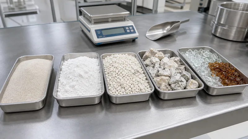 Raw-material identity, chemistry, moisture, particle size and contamination all affect melting behaviour and bottle quality.
| Batch material | Main contribution | Why it is used | What must be controlled |
|---|---|---|---|
| Silica sand | Mostly SiO₂ | The principal network former; it gives the glass its fundamental structure. | Chemical purity, iron level for colour, moisture and particle-size distribution. GPI describes container-glass sand as commonly about 40–140 mesh, but the plant’s own specification governs. |
| Soda ash | Na₂O after reaction | Acts as a flux, lowering the temperature and viscosity needed to melt silica economically. | Purity, loss on ignition, moisture and correct proportion. Excess modifier can reduce chemical durability. |
| Limestone | CaO after decomposition | Stabilises the soda-silica network and improves water resistance and durability. | Carbonate chemistry, particle size and refractory contaminants. |
| Dolomite | CaO and MgO | Adds stabilising oxides and helps tune viscosity, durability and devitrification behaviour. | Ca/Mg ratio, impurities, moisture and size distribution. |
| Feldspar, nepheline syenite or another alumina source | Al₂O₃ plus alkalis | Improves chemical durability and helps control the working range and resistance to crystallisation. | Mineralogy, alkali balance, iron and refractory grains. |
| Cullet | Pre-reacted glass oxides | Melts more readily than virgin batch, recycles internal rejects and can reduce melting energy. | Correct glass family and colour; remove ceramics, stones, metals, organics and heat-resistant glass. Cullet is a controlled raw material, not random broken glass. |
| Minor additions | Refining, colour or redox control | Support gas removal, colour correction or deliberate amber/green/other colour development. | Low-dose weighing, supplier identity, oxidation state and interaction with furnace atmosphere. |
An illustrative oxide composition—not a batch recipe
A representative soda-lime container glass may contain roughly 70–73% SiO₂, 13.8–14.4% Na₂O, 9.1–9.8% CaO, 1.1–1.7% MgO and 1.7–2.0% Al₂O₃, plus small amounts of other oxides. Those government-published ranges are useful for understanding the system; they are not suitable for copying into a furnace. A plant must calculate its own batch from raw-material assays, cullet chemistry, volatile losses, colour target, redox, furnace behaviour and product specification.
Cullet also has a measurable process benefit. FEVE reports an industry estimate of about 2.5% lower furnace energy consumption for each 10% increase in cullet. The actual plant result varies with furnace design, cullet quality, colour constraints and operating practice.
The Temperature Map: Use Viscosity, Not a Magic Number
Temperature matters because viscosity changes steeply as glass cools. The furnace needs a low enough viscosity for reactions, bubble removal and homogenisation. The feeder needs glass viscous enough to cut into repeatable gobs but fluid enough to fill the blank mould. The lehr needs a controlled thermal path that relaxes stress without deforming the bottle.
| Stage or reference | Published example | What the number means | What goes wrong if control is poor |
|---|---|---|---|
| Pure silica reference | About 1,700°C | Corning’s explanation of why sand alone is impractical to melt; soda lowers the required working temperature. | Using this as a bottle-furnace setpoint ignores soda-lime chemistry and equipment. |
| Container melting furnace | About 1,550–1,600°C | Bucher Emhart’s container-production example for a furnace heated by electricity, gas or oil. Other manufacturers publish values around 1,500–1,550°C. | Incomplete dissolution, stones, bubbles or cords if heat, residence time and circulation are insufficient; volatilisation, refractory wear or energy waste if excessive. |
| Forehearth and feeder gob | Often roughly 1,100–1,200°C for container glass | A typical forming window published by container-industry sources; the exact target is chosen from the glass viscosity curve and job conditions. | Gob curl, weight/shape variation, bad loading, poor fill and uneven wall distribution when temperature is wrong or thermally non-uniform. |
| Annealing lehr | About 580°C in Emhart’s container example | A lehr process example: ware is brought through a controlled high-temperature zone and then cooled. It is not the same as the glass composition’s laboratory annealing-point value. | Residual tensile stress, delayed cracking or poor strength if the through-glass temperature and cooling gradient are not controlled. |
Important: furnace thermocouple temperature, glass-bath temperature, optical gob temperature, mould temperature and lehr-air temperature are not interchangeable measurements. A competent process sheet states the location, instrument, emissivity or calibration method, tolerance and reaction plan.
How Glass Is Made Step by Step
1. Define the glass and finished-product specification
Before batching, engineering defines colour, light transmission, chemical durability, thermal expansion, density and viscosity curve, as well as the bottle’s brimful capacity, mass, finish dimensions, wall distribution and strength requirements. The product requirement determines the glass composition and forming route; the furnace does not fix every job by itself.
2. Receive and qualify raw materials
Each delivery is identified and sampled against an incoming specification. Typical checks include chemical assay or certificate verification, moisture, particle size and visual or instrumental contamination control. Cullet requires particularly disciplined sorting: a small ceramic fragment or heat-resistant glass piece may survive the melt and become a stone or local stress source.
3. Store, weigh and mix the batch
Materials move from dedicated silos to calibrated scales. The batch system applies the approved recipe and corrects for moisture where required. Mixing must distribute minor ingredients without allowing coarse and fine fractions to segregate. Dust collection protects workers and prevents loss of fine, compositionally important material.
4. Charge the furnace steadily
A batch charger feeds virgin batch and cullet into the melting end at a controlled rate. Continuous container furnaces are designed around stable pull. Sudden changes in feed, cullet ratio, moisture or glass pull disturb the thermal and residence-time balance, so planned changes should be ramped under a documented recipe and furnace-control plan.
5. Melt and react the batch
Heat drives off moisture, decomposes carbonates, releases gases and forms silicates. Cullet softens earlier and creates liquid pathways that help the virgin particles dissolve. The operator controls heat input, furnace atmosphere, pull, glass level and combustion or electrical parameters. “The batch has disappeared” is not the end of melting: tiny unmelted grains, gases and chemistry gradients can remain.
6. Refine and homogenise the melt
Refining lets bubbles grow, rise and escape while circulation and residence time reduce chemical and thermal inhomogeneity. A stable glass level and temperature field matter as much as the peak temperature. Seeds, blisters, cords and stones are evidence to investigate—not problems to hide later with decoration.
7. Condition the glass in the working end and forehearth
The melt leaves the furnace hotter and less viscous than the forming machine needs. The working end and forehearth cool and equalise it to the job’s forming viscosity. Average temperature alone is insufficient: side-to-centre and top-to-bottom uniformity affect gob shape, loading and wall distribution. Closed-loop heating/cooling and multiple-zone measurements are therefore more useful than one display value.
8. Form the product
The conditioned glass now branches by product. Float glass is floated on molten tin; fibres are drawn; tableware may be pressed or blown; and containers are divided into gobs and formed in moulds. For bottles, the gob’s weight, temperature, length, diameter, trajectory and centred loading are critical inputs.
9. Anneal on a validated time–temperature curve
Forming cools the outside faster than the inside, locking in stress. The lehr establishes a sufficiently uniform through-glass temperature, holds or passes through the stress-relief region, and cools at a controlled rate. Heavy bases, shoulders and abrupt thickness transitions generally need more conservative thermal treatment than thin, uniform walls.
10. Treat surfaces where required
Container lines may apply hot-end and cold-end surface treatments to reduce surface damage and improve line handling. These are functional manufacturing treatments, distinct from later cosmetic decoration such as spraying, frosting, screen printing or metallisation. Treatment identity and level must remain compatible with downstream decoration and product-contact requirements.
11. Inspect, trace and recycle controlled rejects
Automated inspection can screen dimensions, finish geometry, checks, inclusions and appearance at line speed; laboratories add dimensional, capacity, stress and strength verification according to the product plan. Accepted bottles are packed by identified lot. Clean internal rejects can return as controlled cullet; contaminated material must not be allowed back into the batch.
Factory Example: How a Cosmetic Glass Bottle Is Made
Consider a new flint cosmetic bottle with a narrow neck and a pump-compatible finish. This is an illustrative factory workflow, not a claim about one named plant or a universal job sheet.
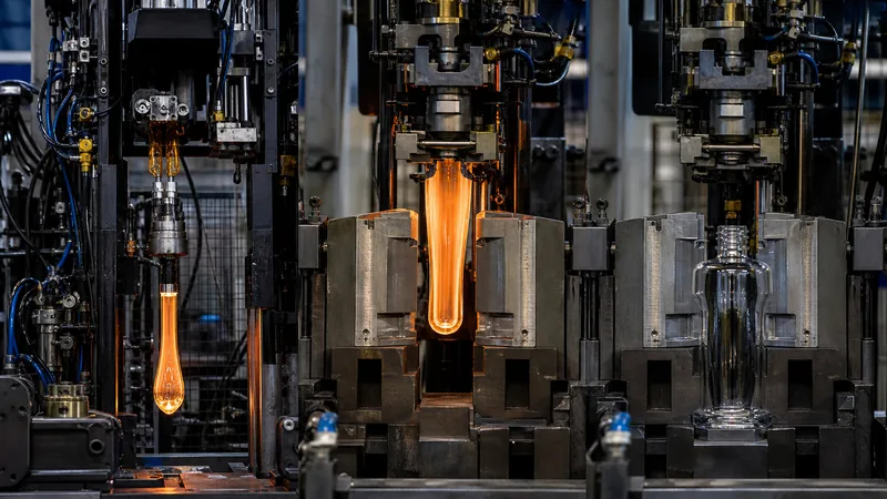 The neck finish is formed and the gob becomes a hollow parison before final blowing establishes the bottle body.
- Product and mould engineering: approve the drawing, glass mass, finish standard, capacity, decoration zones, mould seams, base bearing surface, critical dimensions and forming route. Simulate or trial wall distribution before committing to a production mould.
- Job preparation: qualify the mould set, neck rings, plungers, baffles and bottom plates; confirm cavity identification; load the controlled recipe; and establish the forehearth, feeder, timing, air and cooling settings.
- Gob creation: the feeder meters a stream of conditioned glass and shears a gob corresponding closely to the finished bottle’s glass mass. The line monitors weight, temperature, shape and trajectory.
- Delivery: troughs and deflectors guide the gob into the blank mould. It must arrive at the correct time, orientation and centre. A good gob can still make a bad bottle if delivery equipment is worn, dirty or misaligned.
- Finish and parison formation: the neck ring forms the finish. Compressed air in blow-and-blow, or a plunger in press-and-blow/NNPB, creates the hollow preliminary shape called the parison.
- Invert and reheat: the neck ring transfers the parison to the blow mould. During the short transfer, the surface reheats as heat equalises through the glass. Reheat time and parison temperature distribution influence final wall distribution.
- Final blow: the blow mould closes and air expands the parison against the cavity. Mould cooling removes heat rapidly enough for the bottle to keep its shape after take-out, but must remain balanced to avoid local overcooling and checks.
- Take-out and ware handling: the bottle transfers to the conveyor without hot scuffing, impact or unstable spacing. Cavity identity should remain traceable to inspection data.
- Annealing: bottles pass through the lehr on the approved belt speed and zone curve. Changing bottle weight, base thickness, line speed or spacing may require the curve to be revalidated.
- Cold-end release: inspection separates critical, major and minor defects; dimensions and capacity are checked against the drawing; retained samples and lot records support traceability. Decoration begins only after the undecorated bottle is released.
For the perfume-specific route—including decoration, sampling and OEM sourcing—use Boyu’s separate guide to the glass perfume bottle manufacturing process. Keeping that topic separate prevents this page from duplicating the site’s perfume-production content.
Blow-and-Blow, Press-and-Blow and NNPB
| Route | How the parison is made | Typical fit | Key controls |
|---|---|---|---|
| Blow-and-blow (B&B) | Air forms the finish and counterblows the parison before final blowing. | Long-established route primarily associated with bottles; suitability depends on design and plant capability. | Gob loading, settle blow, counterblow, blank cooling, reheat, final blow and mould venting. |
| Press-and-blow (P&B) | A plunger presses glass into the parison cavity. | Common for jars and wide-mouth containers. | Gob weight, plunger stroke/profile, loading, contact time, plunger cooling and cavity fill. |
| Narrow-neck press-and-blow (NNPB) | A narrow plunger mechanically establishes the internal parison geometry. | Narrow-neck bottles where the design and equipment support controlled lightweighting and wall distribution. | Precise gob weight, plunger motion, thermal condition, neck/shoulder cooling and process repeatability. |
Do not select a route from the bottle name alone. The supplier should demonstrate the actual cavity design, process window, wall-thickness results and strength performance for the proposed bottle. Lightweighting without distribution control can create a bottle that meets average weight but has an unsafe thin zone.
How to Avoid Glassmaking Errors: Diagnose the Process, Not Just the Symptom
Glass-container defects are rarely solved safely by one generic adjustment. The same visible symptom can originate in the batch, furnace, feeder, delivery, machine timing, mould, cooling, ware handling or lehr. Bucher Emhart’s defect guidance explicitly separates causes and remedies by forming process. A useful response therefore starts with containment, cavity/lot correlation and evidence.
| Defect | Likely process families | How to confirm | Prevention and corrective direction |
|---|---|---|---|
| Seeds or blisters small or large gas bubbles |
Batch moisture/chemistry, redox, incomplete refining, furnace disturbance, refractory reaction or forming air entrapment. | Trend by time/cavity; examine bubble size, location and gas/inclusion evidence; compare furnace, batch and job-change records. | Stabilise batch and pull; verify refining temperature/residence and furnace condition; correct gob/parison process if bubbles are introduced during forming. Do not assume every bubble is a furnace bubble. |
| Stones solid inclusions |
Ceramic contamination, unmelted batch, refractory wear or devitrified material. | Microscopy or compositional identification; map frequency by furnace time and location. | Improve cullet/raw-material screening and dissolution; inspect refractory sources; correct thermal zones that permit crystallisation. Treat inclusions with surrounding stress as critical until assessed. |
| Cords or striae composition/viscosity streaks |
Poor chemical or thermal homogeneity, refractory dissolution, forehearth temperature imbalance. | Optical examination; refractive-index or chemical comparison if needed; correlate with forehearth zone data. | Correct mixing, melting, circulation and forehearth balance; locate any refractory source. Cosmetic screening alone does not remove the process cause. |
| Checks fine cracks at finish, shoulder, body or base |
Glass too cold locally, excessive or uneven mould cooling, timing/pressure error, poor equipment match, impact or handling damage. | Locate the crack relative to seams/contact marks; inspect by cavity; review thermal images, cooling, timing and handling contact points. | Contain the affected cavity/lot; correct thermal balance, machine timing, pressure, mould match or contact damage. A check is a structural defect, not an appearance concession. |
| Uneven wall or thin spot | Gob temperature/shape, off-centre loading, parison design, plunger motion, blank cooling, reheat or final blow. | Wall-thickness map by cavity and height; bottle mass; gob radar data; thermal profile; section timing. | Fix the distribution mechanism, not average mass alone. Centre delivery, stabilise gob and plunger, rebalance cooling/reheat and verify the mould/parison design. |
| Shear marks or loading marks | Shear condition/lubrication, gob shape, wet or dirty delivery equipment, misalignment or friction. | Compare mark orientation with shear and delivery path; inspect cut, spray, trough, scoop and deflector. | Maintain the shear and controlled spray; keep delivery equipment clean, dry, correctly sized and centred; remove worn surfaces. |
| Leaner, rocker or out-of-shape base | Hot/soft take-out, uneven mould cooling, bottom-plate condition, ware-handling distortion or poor base design. | Base-plane and verticality measurement by cavity; thermal/cooling trend; conveyor contact observation. | Stabilise take-out temperature and handling; correct mould/bottom-plate cooling and condition; confirm design bearing surface. |
| Finish defect sealing surface, bore, thread or bead |
Neck-ring/plunger wear, poor match, dirt, bad gob loading, thermal imbalance or dimensional drift. | Finish gauges and vision results by cavity; mould-shop records; component wear and match inspection. | Maintain matched mould equipment; verify gauges and critical dimensions; stop release for sealing-surface checks or damage that can create leakage or breakage. |
| High residual stress | Wrong lehr curve or speed, uneven loading/spacing, burner or fan imbalance, bottle geometry/weight change. | Polarised strain examination using an agreed method; confirm actual ware temperature, belt speed and zone uniformity. | Revalidate the lehr curve for the job; repair zone imbalance; control spacing and transitions. Do not rely only on lehr-air display temperatures. |
A disciplined troubleshooting sequence
- Contain: stop or segregate the affected cavity, time window and pallet range when safety, sealing or critical dimensions may be involved.
- Classify: use an agreed defect name, location, size and severity; photograph against a scale and record mould/cavity identity.
- Localise: one cavity suggests mould or section causes; all cavities suggest shared feeder, glass, lehr or inspection causes; a time-linked wave suggests a process disturbance.
- Compare signals: gob weight/temperature/trajectory, plunger stroke, mould temperatures, timing, pressure, cooling, lehr curve and inspection trend.
- Change one controlled factor: record the adjustment and wait the appropriate process response time. Multiple simultaneous changes destroy cause-and-effect evidence.
- Verify and release: demonstrate sustained recovery across the defined sample and time window; disposition the contained material; preserve the root-cause and corrective-action record.
A Practical Factory Control Plan
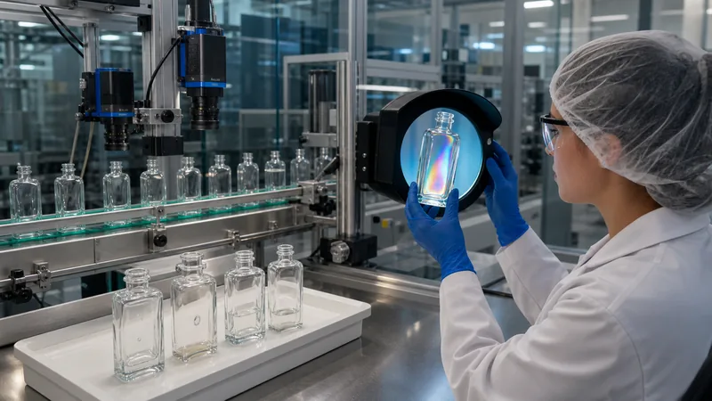 Cold-end inspection is most powerful when each result can be traced back to its mould cavity and hot-end process data.
| Control gate | Measure or verify | Why it predicts quality | Required reaction |
|---|---|---|---|
| Incoming materials | Identity, assay/certificate, moisture, particle size, cullet colour and contaminants. | Prevents composition drift, segregation and unmeltable inclusions before they enter the furnace. | Quarantine nonconforming deliveries; never “blend away” an unidentified contaminant without an approved technical disposition. |
| Batch house | Scale calibration, recipe version, actual weights, moisture correction, mixer cycle, batch traceability. | The furnace cannot consistently correct a wrong or segregated batch. | Interlock out-of-tolerance weights; retain electronic batch records and authorised recipe changes. |
| Furnace and glass | Pull, glass level, zone temperatures, energy/air/fuel or electrical input, redox/colour, density and defect trend. | Shows whether melting, refining and composition remain stable. | Use slow, authorised corrections; link disturbance timing to downstream residence time before releasing affected ware. |
| Feeder and gob | Temperature profile, gob weight, length, diameter, shape, shear quality and trajectory. | These are the forming machine’s direct material inputs. | Correct thermal balance, feeder mechanism, shear or delivery before compensating with unrelated machine settings. |
| IS machine by cavity | Timing, pressure, plunger motion, mould temperature/cooling, equipment condition, mass and wall map. | Reveals section-to-section variation that a lot average conceals. | Contain the cavity; repair or reset; prove capability after job change and maintenance. |
| Lehr | Recipe, zone/belt conditions, speed, loading pattern, ware temperature evidence and residual stress. | Confirms that the glass—not merely the lehr air—received the intended heat treatment. | Hold affected time bands when a zone, fan, burner, belt speed or loading deviation can alter stress. |
| Cold end and laboratory | Critical defects, finish, dimensions, capacity, verticality, base, appearance, stress and specified strength/function tests. | Protects the customer and feeds evidence back to the process. | Reject critical defects at 100% where appropriate; apply the approved sampling plan to lot attributes; investigate trends before limits are exceeded. |
Finished bottles still need a project-specific validation program. For a broader view of dimensional, sealing, compatibility, transport and functional checks, see what tests are required for cosmetic bottles. In-process control makes good bottles; finished-package testing confirms the bottle, closure, formula and distribution system work together.
What a Buyer Should Ask a Glass Bottle Factory
- Which legal entity and physical plant melts and forms the glass, and which company performs decoration?
- What glass composition/colour family and forming process will be used for this SKU? Is the proposal blow-and-blow, press-and-blow or NNPB?
- What are the controlled gob-weight, temperature-uniformity and wall-distribution criteria? Ask for tolerances and capability evidence, not one target value.
- How are cullet and raw materials screened against ceramic, metal, organics and wrong-glass contamination?
- Can inspection data be traced to furnace, line, time, mould and cavity? How is a suspect time window contained?
- How is the lehr recipe validated after a bottle-weight, geometry, speed or loading change? What residual-stress method is used?
- Which finish dimensions are critical for the selected pump or closure, and which gauges or vision checks verify them?
- Which defects are classified as critical, major and minor, and which receive 100% automated screening?
- What is the sample approval path—drawing, pilot mould or trial, undecorated golden sample, decorated sample and production release?
- What change-control events require buyer approval: glass colour/composition, mould, cavity repair, forming route, plant, surface treatment or decoration vendor?
A useful factory document set
Request the controlled bottle drawing, finish standard, defect limit sample, material/colour declaration, forming and inspection flow, cavity traceability example, dimensional and capacity report, wall-thickness map, strain/annealing evidence, relevant strength results, packing specification and signed change-control agreement. Photos of a furnace are not a substitute for records tied to your SKU.
Frequently Asked Questions
Is glass made from sand alone?
No. Silica sand is the main network former, but pure silica requires extremely high processing temperatures—about 1,700°C in Corning’s explanation. Soda ash acts as a flux, limestone/dolomite add stabilising oxides, an alumina source tunes durability and working behaviour, and controlled cullet helps melting. Minor additions manage refining, redox and colour.
What temperature is needed to make glass?
There is no single temperature. A soda-lime container furnace is commonly described around 1,500–1,600°C, while the glass is conditioned to a lower forming window—often around 1,100–1,200°C for the gob—and annealed near the glass-specific stress-relief range. The correct value comes from composition, viscosity, measurement location, equipment and product geometry.
How long does industrial glass take to make?
Container furnaces run continuously, so glassmaking is not a fixed one-batch timer. Residence through melting/refining can be many hours and depends on furnace design and pull; one major manufacturer, Verallia, describes about 24 hours for raw materials to become homogeneous glass in its process. Forming itself takes seconds per container, and annealing proceeds continuously through a lehr. Use plant residence-time and traceability data for the actual line.
Why are glass bottles annealed?
The mould cools the outer surface faster than the interior. Without controlled reheating/equalisation and cooling, damaging residual tensile stress can remain. Annealing lets stress relax, then cools the bottle slowly enough to avoid generating new gradients. The lehr curve must match glass composition, thickness distribution, bottle mass, speed and loading pattern.
Can defective bottles go back into the furnace?
Clean internal rejects of the correct glass family and colour can usually be crushed and managed as cullet. The return loop must exclude metal, ceramics, organic contamination, refractory fragments, wrong colours and incompatible heat-resistant glass. “Recyclable” does not mean any broken item can be charged without control.
What causes a glass bottle to crack after production?
Possible causes include a forming check, impact damage, a sharp inclusion, excessive residual stress, poor wall distribution, thermal shock or later closure/handling load. Diagnose crack origin and stress pattern rather than blaming “bad annealing” automatically. Contain the relevant cavity and time window until the mechanism is confirmed.
Can glass be made safely at home?
Not by following this industrial process. Soda-lime melting involves extreme temperature, corrosive molten material, off-gases, refractory systems and specialised protective and ventilation controls. Studio glasswork should be learned in a properly equipped facility under qualified supervision; a container-factory recipe cannot be scaled down safely as a casual DIY project.
Need a glass cosmetic bottle that is manufacturable—not just attractive?
Send Boyu Packaging the fill volume, bottle reference or drawing, formula category, closure/finish, target glass colour, decoration, annual demand and destination market. We can help turn the concept into a supplier-ready specification and coordinate samples and validation. Explore cosmetic glass packaging or contact Boyu Packaging.
Sources and Verification Links
Sources were accessed in August 2026. Published temperatures are examples tied to the cited glass or process; they are not universal operating instructions. Final job settings must be established and validated by the responsible glass manufacturer.
- Bucher Emhart Glass — Making Glass Containers
- Bucher Emhart Glass — Glass Container Defects Guide
- Bucher Emhart Glass — Forming Process Measurement and Control
- Glass Packaging Institute — What Is Glass?
- Glass Packaging Institute — The Role of Sand in Glass Container Manufacturing
- FEVE — Cullet, Recycled Content and Furnace Energy
- Corning — How Glass Is Made
- U.S. Federal Highway Administration — Typical Soda-Lime Glass Composition
- U.S. EPA AP-42 Section 11.15 — Glass Manufacturing
- Vidrala — Glass Container Production Process
- Verallia — Stages of Glass Manufacturing
- BDF Industries via glassglobal — Forehearth, Gob and IS Forming Overview


 English
  Español de Argentina
  Русский
  Italiano
  日本語
日本語  한국어
한국어  العربية
  Français
  Deutsch