

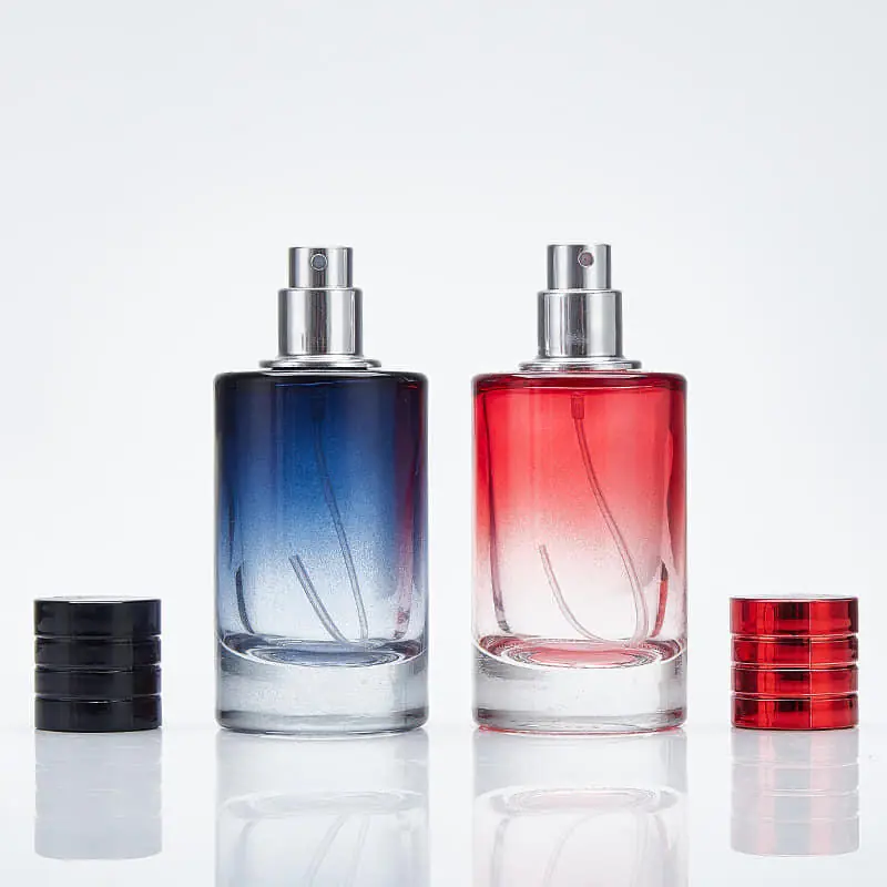
Direct answer: a cosmetic bottle can pass hand filling yet jam, tip or leak on an automatic line because the hand sample proves only basic fit and function under gentle, one-at-a-time handling. A production line adds empty-bottle instability, conveyor acceleration, accumulation pressure, transfers, timing screws or starwheels, multi-cavity dimensional variation, fast filling, closure feeding and controlled capping torque. Diagnose the first abnormal event at a specific station, then separate five cause families: container geometry, pump or closure, formula behaviour, machine setup and lot variation. Do not accept “run slower” as the final corrective action unless the validated operating speed is intentionally changed.
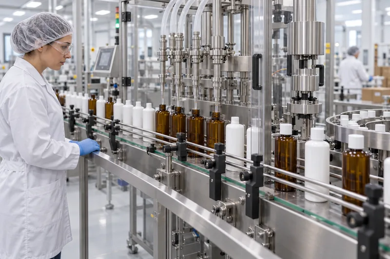
Why does a hand-approved cosmetic pack fail on an automatic filling line?
The missing concept is machinability: the ability of the bottle, formula, closure and line to operate together at the intended rate and within defined settings. A bottle may meet its drawing and still be a poor match for one conveyor layout. Conversely, a line can be incorrectly set for a fully conforming bottle. The investigation must therefore test the package and the process as a system.
| What the hand sample hides | What the automatic line adds | Typical failure revealed |
|---|---|---|
| An operator selects and holds each bottle. | Empty bottles must stand unsupported through rails, curves, gaps and speed changes. | Rocking, tipping, scuffing or double-feeding. |
| A nozzle is centred by eye and filled slowly. | Several nozzles must enter or align repeatedly while liquid accelerates and cuts off quickly. | Neck strike, foam, splashing, stringing, drips or under/overfill. |
| A closure is presented squarely and its thread start is felt by hand. | A feeder, chute and placement head must orient the part; a chuck or spindle must engage and tighten it. | Cross-thread, cocked pump, missed cap or damaged neck. |
| A few attractive prototypes are checked. | Production uses multiple mould cavities, lots, shifts and decorated components. | Intermittent faults tied to one cavity, pallet or supplier lot. |
| A filled and closed sample rests upright. | The pack sees wet seal lands, torque, stop/start cycles, accumulation, case packing and transport. | Leakage after capping, torque relaxation or actuator discharge. |
This is why ten hand-filled samples are not a line trial. A useful approval ladder is: appearance sample → bench-functional sample → production-intent engineering samples → line-trial quantity → controlled initial production lots. Each stage answers a different risk question.
Use a five-part diagnostic method before changing the line
Start with evidence, not a debate over whether the bottle or filler is “at fault.” The fastest investigations identify the first disturbance and change one factor at a time.
- Freeze and map the event. Record line speed, SKU, formula temperature, component lots, machine recipe, time and exact station. Slow-motion video should begin upstream of the visible jam or leak; the bottle that falls is often reacting to an earlier rail contact or transfer gap.
- Classify the cause family. Check container geometry/material, closure/pump/dip tube, formula/fill physics, machine format parts/settings and incoming variation.
- Measure the interfaces. Compare bottle base, diameter, height, neck, bore, ovality and mass with the controlled drawing; use the correct datum and procedure when measuring a cosmetic bottle neck finish. Then measure guide locations, transfer gaps, nozzle alignment, fill profile, closure placement and applied torque using appropriate calibrated equipment.
- Run a crossover trial. Test a known-good bottle on the current setup and the suspect bottle using controlled settings. Where possible, exchange only one element—bottle lot, pump lot, formula batch or format set—while holding the others constant.
- Verify the correction across the window. Demonstrate performance at defined low/nominal/high speeds, stop/start and accumulation conditions, relevant formula temperatures and representative component cavities or lots. Document the final machine recipe and component revision.
If failures follow one bottle mould cavity or one pump lot, suspect incoming variation. If every bottle fails at one physical station, suspect the station or its interface. If the failure appears only above a certain speed, investigate dynamics, spacing and control timing—but still check whether component variation is shrinking the available operating window.
Audit the line in product-flow order
When the visible fault is near the filler, teams often start adjusting the filler. A more reliable audit follows the container from depalletizing or unscrambling to the finished case. At each station, record the incoming state, the contact surfaces, the change in speed or orientation, the expected output and the reject signal. This prevents a downstream symptom from being assigned to the wrong machine.
| Station | Critical package–machine interfaces | Evidence of a developing fault |
|---|---|---|
| Bulk supply / unscrambler | Bottle stiffness, static, nesting, orientation features, decoration protection and discharge rate. | Bridging, double discharge, scratches or intermittent surges that overload the next conveyor. |
| Conveying / accumulation | Base contact, belt friction, rail clearance/contact height, curves, speed ratios, gaps and back pressure. | Bottle rotation, rocking, visible body compression, growing line pressure or repeated scuff marks. |
| Metering / spacing | Timing-screw or starwheel pitch, phase, pocket profile, sensor timing and arrival pressure. | Bottles enter a pocket late, rebound, rotate or show a repeatable contact mark. |
| Filling | Bottle centring, neck bore, nozzle outside diameter/travel, fill profile, headspace and formula condition. | Nozzle strike, eccentric wetting, foam, drip, strings or head-specific fill drift. |
| Pump/cap placement | Feeder orientation, chute release, closure outside profile, dip-tube trajectory and bottle neck position. | Cocked closure, dip-tube snag, bounced cap, missing component or product transferred to the seal land. |
| Capping / crimping | Thread start, chuck/spindle alignment, bottle restraint, applied torque or crimp geometry and top load. | Bottle spin, panel collapse, cross-thread, uneven closure height, thread damage or seal contamination. |
| Inspection / labelling / case pack | Reject timing, sensor contrast, label pressure, actuator lock, pack dividers and case clearance. | False rejects, label skew from bottle rotation, unlocked pumps, abrasion or case-triggered dispensing. |
Mark the bottle before slow-motion recording
Place a removable orientation mark on the shoulder and record the mould cavity where traceable. The mark reveals whether the bottle rotates before a jam and whether one side consistently contacts a rail or nozzle. Pair video with retained samples: label each failed bottle with station, time, line speed, lot/cavity and failure mode. Without this link, later dimensional measurements cannot be connected to the event.
Check the restart, not only steady running
Many faults occur when an upstream machine releases accumulated bottles, a filler restarts with product still at the nozzle, or a cap feeder recovers from a low-level condition. Record the seconds before and after a normal stop. Confirm that speed commands, spacing devices, no-bottle/no-fill logic, pump/cap placement and rejects return in the correct sequence.
Why do cosmetic bottles jam on the filling line?
“Jam” describes the symptom, not the root cause. Determine whether the bottle stops because it is too large or distorted, arrives at the wrong pitch, encounters a bad transition, is squeezed by accumulated containers, or collides with a nozzle, timing screw, starwheel, puck or closure-placement component.
| Observed pattern | Likely mechanisms | Evidence to collect | Corrective direction |
|---|---|---|---|
| Bottle pinches between rails | Rail gap too narrow, rails not parallel, body ovality, decoration build or sidewall distortion. | Body width at several heights and 90° orientations; rail spacing along the path; scuff location. | Restore bottle/decoration tolerance or reset rails at a repeatable datum; do not widen blindly and create tipping. |
| Jam at a conveyor transfer | Excessive gap, height mismatch, dead-plate friction, speed mismatch or unstable base. | Close video of the leading base edge; conveyor levels and speeds; base flatness/rock. | Smooth the transfer and speed ratio; correct the base or use suitable stabilization/format parts. |
| Jam entering a timing screw or starwheel | Incorrect pitch, phase, change part or infeed pressure; bottle outside the format envelope. | Arrival spacing, screw/starwheel revision, phase setting, bottle contact marks and line recipe. | Install the approved format set and synchronize infeed; control accumulation pressure. |
| Jam only after pump insertion | Long/bowed dip tube, cocked pump, loose actuator orientation, increased overall envelope. | Assembled height/width, dip-tube free length and cut, pump orientation, insertion video. | Correct presentation and insertion; validate the dip-tube length. |
| Intermittent jam from one carton/pallet | Cavity, lot, conditioning, pack-out deformation, static or surface-friction variation. | Retain jammed parts with cavity/lot traceability; dimensional and surface comparison with good parts. | Contain the affected lot, correct manufacturing or pack-out variation, then reconfirm line performance. |
Why do bottles tip over, and how should stability be improved?
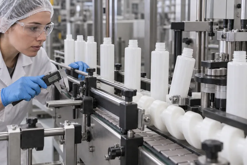
Empty cosmetic bottles are most vulnerable because their mass is low, while a tall shoulder or neck raises the effective centre of gravity. A narrow base, rocking push-up, uneven heel, asymmetrical shape or flexible wall further reduces the stable operating window. Sudden conveyor acceleration, curves, side contact, back pressure and transfer gaps supply the disturbing force.
A simple engineering model explains the trend. The restoring moment is approximately bottle weight × half the effective support width. The overturning moment increases with lateral acceleration × bottle mass × centre-of-gravity height. This model is useful for comparing designs, but it is not a universal pass/fail equation: rail contact, friction, liquid motion, bottle flexibility and machine geometry also matter.
Correct instability in this order
- Confirm the base. Check coplanarity, rocking, push-up and mould-parting effects on production parts. A bottle that rocks on a flat plate is unlikely to become reliable through rail pressure alone.
- Remove abrupt dynamics. Align and level transfers; synchronize adjacent conveyor speeds; reduce unnecessary gaps; tune acceleration/deceleration and upstream accumulation.
- Place guide contact intelligently. Support a stable body region without contacting a highly flexible panel or pushing above the point that promotes rotation. There is no single correct guide-rail height for every bottle.
- Use positive handling when needed. Timing screws, starwheels, neck handling or transport pucks can control spacing and normalize irregular or top-heavy formats. Equipment manufacturers such as groninger explicitly offer transport cups for unstable cosmetic containers; the correct device must match the actual line.
- Redesign when the window remains fragile. A wider effective base, lower centre of gravity, controlled wall distribution or less extreme height-to-base ratio can produce a more robust commercial pack than continual line compensation.
Do not simply tighten both rails. Excessive side pressure can create scuffing, rotation, body deformation and a new jam. Pressureless or low-pressure accumulation is often used to reduce container-to-container compression, but it does not correct an out-of-tolerance base or unsuitable format part.
Why does the line produce leaking cosmetic bottles?
First decide whether the liquid is an external spill created during filling or a sealed-package leak that emerges after closure application. Wiping a bottle without locating the source can turn a nozzle-drip problem into a false closure complaint.
| Leak timing/location | Likely causes | Practical checks and fixes |
|---|---|---|
| Wet shoulder immediately after filling | Nozzle off-centre, late cut-off, dripping/stringing, splash, foam overflow, incorrect fill height or bottle not positively located. | Observe each nozzle; inspect shut-off; centre the container; tune acceleration/deceleration and suck-back; use bottom-up/diving filling where appropriate; leave validated headspace. |
| Leak from thread or seal after capping | Product on sealing land, cross-thread, cocked closure, wrong liner/gasket, neck ovality/flash, inadequate or excessive applied torque. | Inspect dry versus wet necks; section the assembly if needed; verify full neck-finish and closure compatibility; control placement, thread start and torque by closure/neck supplier recommendations and package validation. |
| Pump lifts, tilts or will not seat | Dip tube too long or wrong angle, closure not presented squarely, neck bore/finish variation or poor pre-screw engagement. | Compare assembled geometry, tube interference and insertion force; use controlled pre-screwing/thread-start then final torque where equipment supports it. |
| Leak develops after hours/days or transport | Torque relaxation, liner creep, formula attack/swelling, pressure/temperature effect, stress crack, seal damage or pump vent path. | Measure removal torque over time; run validated orientation/pressure/transport tests; inspect compatibility exposure. Use Boyu’s guides to cosmetic bottle leak testing and formula–package compatibility. |
| Actuator dispenses in the case | Actuator left unlocked, inadequate overcap/lock, pack-out compression or insufficient case clearance. | Verify actuator state at pack-out, shipping clearance and compression; test the packed configuration, not only the individual bottle. |
Formula and filler settings: foam, stringing and fill-weight variation
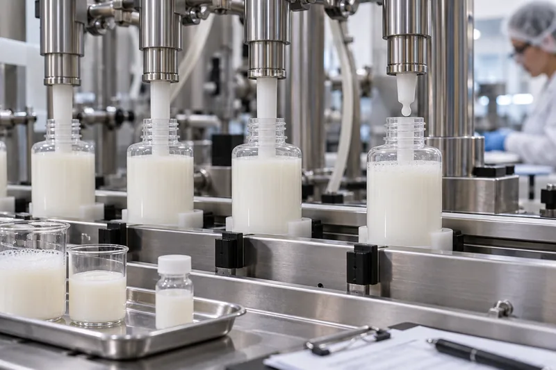
The bottle may be dimensionally correct while the fill profile is wrong for the formula. Viscosity changes with formula and temperature; entrained air can make a volumetric dose appear high; surfactants can foam; gels and lotions may form strings after nozzle cut-off. The filler type, nozzle bore, dive motion, fill speed by stroke segment, cut-off and suck-back must suit the product.
- Foaming: reduce free-fall distance, consider a diving nozzle that follows the rising fill level, slow the high-foam portion of the profile and control deaeration/temperature where the formula process permits.
- Stringing or tailing: inspect the nozzle shut-off, product temperature and velocity; optimize cut-off/suck-back without drawing air or compromising dose.
- One nozzle differs: analyze fill mass by individual head, not only the overall average. Check calibration, trapped air, valve timing, tubing restriction, piston/seal condition or load-cell setup.
- Fill level varies but mass does not: bottle internal volume or wall distribution may vary. A visual fill line is not necessarily a mass error.
- Mass varies with temperature: volumetric filling can change delivered mass as density changes. Define whether release is controlled by mass, volume at a stated reference condition, fill height or a combination.
For US net-content compliance, NIST Handbook 133 provides official test procedures and sampling plans used by weights-and-measures officials. It is not a substitute for the packer’s process-control plan. OIML R 87 similarly states that its sampling plans are not intended to prevent packers from using other quantity-control procedures. Build routine controls around the process capability and legal requirements for the destination market.
How to run a useful cosmetic packaging filling-line trial
A successful trial uses production-intent material and predefined decisions. It should expose the intended operating window, not produce a short video of carefully fed bottles at reduced speed.
A supplier’s approved appearance sample is a visual reference, not proof of cavity-to-cavity or lot-to-lot machinability. If trial bottles are individually selected, hand packed or made on pilot tooling, they can underrepresent base rock, body ovality, neck position, surface friction and decoration variation. Ask how the trial pieces were produced and sampled. Include normal production cavities, start-up and steady-state material where justified, final pack-out conditioning and the intended decoration route. Keep the best-looking master sample for appearance decisions, but use a statistically and technically representative set for line decisions. This distinction prevents a visually perfect piece from becoming the only physical specification for a high-speed process.
1. Bring representative components
Use bottles from the intended production process, across relevant cavities and pallets—not only hand-selected golden samples. Include final decoration, actual closure/pump, gasket or liner, cut dip tube, overcap and shipping pack-out. Record every lot and cavity identifier available.
2. Use the actual formula at relevant conditions
Water can screen basic mechanical handling, but it does not represent a lotion’s viscosity, a toner’s surfactant foam, a fragrance’s wetting behaviour or a gel’s stringing. Run the real formula at justified low/nominal/high temperature or viscosity conditions when those variables materially affect filling.
3. Qualify by station, then as an integrated line
Begin with dry bottle handling and correct mechanical format parts. Add filling, pump/cap feeding, insertion, pre-screw, final capping, coding/labeling and case packing. A component can pass each isolated station but fail at the interface between them; finish with a continuous integrated run.
4. Challenge realistic disturbances
Include start/stop, accumulation release, replenishment of closures, normal operator interventions, line ramping and changeover where relevant. A short steady-state run may never create the back pressure or spacing error that causes field production losses.
5. Close the trial with controlled outputs
Approve a machine recipe, format-part list and setup references; identify unresolved deviations; retain representative samples; assign actions and owners; and state whether approval covers the exact tested line, formula, speed range, package revision and component sites/lots. Integrate the line trial into the broader cosmetic bottle test plan, because line machinability does not replace compatibility, dispensing, mechanical or distribution evidence. FDA’s cosmetic GMP inspection checklist emphasizes suitable equipment, written manufacturing and filling instructions, approved materials, in-process controls and records—disciplines that support repeatable production rather than memory-based setup.
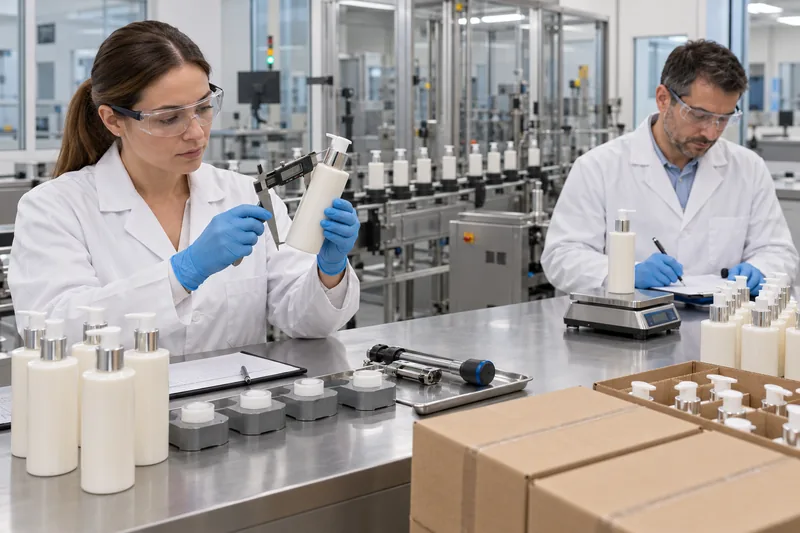
What belongs in a pack–line interface specification?
A drawing controls the package; a machine recipe controls the line. The interface specification connects them. At minimum, exchange the following before tooling or ordering high-volume components:
- Bottle: material, nominal/brimful capacity, dimensions and tolerances at rail/starwheel contact zones, total height, base geometry, mass range, neck finish, bore, sealing land, ovality controls, cavity identification and decoration envelope.
- Closure or dispenser: outside envelope, orientation needs, thread/snap/crimp interface, seal system, dip-tube specification, applied/removal torque or crimp specification, actuator lock state and feedability requirements.
- Formula: density, viscosity test method and temperature, fill temperature, foam/stringing tendency, particulates, compatibility constraints, required dose/net contents and headspace.
- Line: target and qualified speed range, conveyor height/transfers, handling principle, format parts, nozzle diameter/travel, closure feeding/placement, capping method, inspection/reject systems and cleaning constraints.
- Quality evidence: sampling by cavity/lot, dimensional report, approved master samples, leak/compatibility protocol, fill and torque data, jam/tip/reject log, deviation disposition and change-control route.
Never specify only “24 mm neck” or “matching pump.” The complete neck finish, bore, sealing system, closure geometry and controlled drawings matter. A nominally matching part can screw on by hand and still misfeed, cross-thread or leak under automatic application.
How should line-trial acceptance criteria be set?
There is no universal cosmetic-industry limit such as “one jam per 10,000 bottles” that fits every line, package and business risk. Define criteria before the trial from regulatory needs, equipment capability, expected output, quality risk and commercial loss. Avoid declaring success because the team managed to complete the run.
| Metric | Record it this way | Why totals alone mislead |
|---|---|---|
| Jams/tips/stops | Count by cause, station, operating state, component lot/cavity and number processed. | Ten stops at one rail require a different fix from ten unrelated operator interruptions. |
| Fill quantity | Mean and variation by nozzle/head, time and formula condition; include tare method. | The overall mean can hide one low and one high filler head. |
| Closure application | Cocked/missed/cross-threaded count, application settings, removal torque where meaningful and seal result. | A torque reading cannot prove that a contaminated or damaged seal is leak-tight. |
| Leakage | Use a defined method, orientation, time, temperature/pressure and failure location. | “No leak observed” is not reproducible without test conditions. |
| Damage/appearance | Scuff, dent, crack, decoration loss and contamination against approved visual criteria. | A line can run without stopping while silently damaging saleable appearance. |
Corrective-action priorities: contain, correct, then prevent recurrence
- Protect current product. Stop or segregate affected output, identify the last known good point and retain failed parts. Reinspect only with a defined method; wiping leaks and returning packs to stock destroys evidence.
- Restore the approved baseline. Confirm component revisions, line format parts, recipe, calibration, cleaning/assembly status and formula condition before improvising adjustments.
- Remove the verified cause. Correct the out-of-tolerance package, transfer, guide, timing, nozzle, closure placement, capping or pack-out factor supported by the trial.
- Validate the new window. Re-run enough representative product to include normal variation, start/stop and accumulation. A ten-bottle confirmation is rarely persuasive for an intermittent fault.
- Make the improvement durable. Update drawings/specifications, line recipe, setup aids, inspection plan, supplier controls, operator training and change-control records.
If reducing speed is the only immediate safe containment, document it as a temporary operating limit and quantify the new capacity. Then continue the root-cause investigation. Otherwise the fault often returns with the next lot, shift or format change.
Checklist for brands, fillers and packaging buyers
- Send line constraints and target speed to the packaging supplier before final bottle tooling or decoration approval.
- Request production-intent samples that represent cavities and normal process variation; do not rely only on prototypes or selected pieces.
- Define machinability, appearance, fill quantity, sealing, dispensing and packed-distribution requirements separately.
- Control the complete bottle, pump/closure, liner/gasket, dip tube, overcap and decoration—not isolated catalogue numbers.
- Agree who owns line trials, quantities, actual formula, format parts, measurement equipment and corrective actions.
- Retain failed and good samples with line-station, time, component lot/cavity and formula-batch traceability.
- Require prior review when resin, component construction, tooling, cavity set, manufacturing site or critical processor changes.
- Before a repeat order, compare the line-trial baseline with current drawings, approved samples and supplier declarations.
Boyu Packaging can review bottle, dispenser and closure interfaces with your filler’s line constraints before mass production. For a project-specific sample and validation discussion, contact the Boyu Packaging team with the formula type, target fill volume, closure system, intended line speed and available equipment drawings.
Frequently asked questions
Does passing a bottle drawing guarantee it will run on the filler?
No. Drawing conformance is necessary, but it does not by itself prove stability through the actual conveyor, compatibility with format parts, nozzle clearance, closure feedability or performance at target speed. Line qualification proves the package–machine interface.
Can water be used instead of the cosmetic formula for a trial?
Water is useful for basic bottle handling and an early wet screen, but it cannot validate viscosity-dependent dosing, surfactant foam, gel stringing, wetting, compatibility or final leakage. Use the actual formula—or a scientifically justified surrogate—for the relevant qualification stage.
Should guide rails touch cosmetic bottles?
They normally guide and constrain the container, but the required clearance and contact height depend on bottle geometry, flexibility and handling method. Rails that squeeze the body can cause scuffing, deformation and jams; excessive clearance can permit rocking. Establish repeatable settings during the line trial.
Are transport pucks always the best answer for unstable bottles?
No. Pucks are valuable for irregular, narrow-base or top-heavy packs and can standardize the line’s handling diameter, but they add equipment, loading/unloading, cleaning and change-part considerations. First correct base defects and poor transfers; then compare puck handling with bottle redesign or other positive-handling options.
What sample quantity is enough for a filling-line trial?
There is no universal quantity. The run must be long and broad enough to represent cavities/lots, target speed, normal start/stop, accumulation, closure replenishment and relevant formula conditions, while producing enough data per filler/capper head to assess variation. Define the rationale and acceptance criteria before ordering samples.
Who owns a line failure: the packaging supplier or the filler?
Ownership follows the verified cause. An out-of-tolerance base or neck belongs with component manufacture; wrong rails, format parts or timing belongs with line setup; foam may require formula and filler changes. Many failures are interface problems, so the brand should require a joint, evidence-based investigation rather than assign blame from the symptom.
Sources and technical references
Accessed 2 October 2026. Manufacturer examples describe available engineering approaches; they are not universal specifications for every line.
- US FDA — Good Manufacturing Practice (GMP) Guidelines/Inspection Checklist for Cosmetics
- ISO 22716:2007 — Cosmetics, Good Manufacturing Practices
- NIST — Handbook 133, Current Edition
- NIST — Net Contents of Packaged Goods FAQs
- OIML R 87:2016 — Quantity of Product in Prepackages
- Sidel — Pressure-less Accumulation
- Sidel — Conveying Solutions
- groninger — Cosmetic Filling Machines
- groninger — Filling and Closing Solutions for Skin Care
- groninger — flexcare 100 Filling and Closing Machine
- Cozzoli — VR840 Inline Filling Machine Technical Sheet
- Packaging World — Empty-Bottle Handling Is No Picnic


 English
  Español de Argentina
  Русский
  Italiano
  日本語
日本語  한국어
한국어  العربية
  Français
  Deutsch